Model 458-SM Transparent Switching Module

Model 458-SM Transparent Switching Module

Model 458-SM Transparent Switching Module is a transparent, electrically neutral, multiplexing/demultiplexing device that allows up to sixteen incoming lines to share (be directed to) up to two independent local loop simulator output channels, or two incoming lines to share (be directed to) up to sixteen independent local loop simulator output channels. The user may select one or two of the inputs (or outputs) out of sixteen, with the unselected paths being terminated with 100 ohms.

Main Features
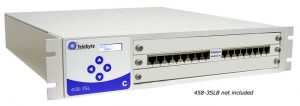
The Model 458-SM-16 from Telebyte Broadband
  • High Performance transparent solution designed to automate testing of ADSL, ADSL2, ADSL2+, & VDSL2 chip/ modem/ DSLAMs
  • Bidirectional
  • Low Cross talk/ Low Insertion Loss
  • Plugs into Model 458-CC-16/458-CM (16-slot) or 458-3SLB (3-Slot) rack-mounted chassis
  • Can be controlled remotely via RS-232, Ethernet or IEEE-488 (GPIB)


Product Overview

The Model 458-SM-2-16 Transparent Switching Module is a transparent, electrically neutral, multiplexing/demultiplexing device that allows up to sixteen incoming lines to share (be directed to) up to two independent local loop simulator output channels, or two incoming lines to share (be directed to) up to sixteen independent local loop simulator output channels. The user may select one or two of the inputs (or outputs) out of sixteen, with the unselected paths being terminated with 100 ohms.

This powerful module is plugged into our Model 458-3SLB (3-Slot) or 458-CC-16/458-CM (16-Slot) rack-mounted chassis where settings are controlled by RS-232, Ethernet or IEEE-488(GPIB). The modular design of Telebyte’s products allows the 458-SM-2-16 to be combined with our local loop simulator products for a wide variety of test configurations.

Product Specifications

Model 458-LM-E8-36 Simulator
Simulation Accurately simulates attenuation and impedance
Full bidirectional operation at all specified frequencies
26 AWG PIC as specified in ANSI T1.417
Bandwidth DC to 4.5 MHz
Attenuation Accuracy
(when source and load
impedances are 100 ohms)
MAE < 1 dB 25 kHz to 4.5 MHz
+/- 1 dB channel-to-channel uniformity
Maximum Attenuation >90 dB
Impedance Accuracy Typically +/- 10% 25 kHz to 4.5 MHz
Maximum Voltage Tip ?Ring 200 V
Maximum DC Current 130 mA
Connectors 8 RJ-45’s on front, 8 RJ-45’s on back

Specifications are subject to change without notice. Made in USA